Back
Project log

Control-Moment Stabilising Robot

A self-balancing platform that uses two spinning flywheels and rapid gimbal changes to generate stabilising torques.

Control moment stabilising robot on test rig

Core idea

Angular momentum control

Actuation

Flywheel + gimbal servo

Control

IMU feedback + PID tuning

1) What is control-moment stabilisation?

Control-moment stabilisation uses a rapidly spinning flywheel mounted on a gimbal. The flywheel spins at a constant speed, storing angular momentum. When the gimbal rotates, the direction of this angular-momentum vector changes, and this change generates a torque perpendicular to both the flywheel spin axis and the gimbal axis. This torque can be used to counteract disturbances and stabilise the robot as it begins to tip.

  • Flywheel speed sets how much stabilising authority you have
  • Gimbal angle + rate controls the direction and strength of the corrective torque
  • IMU feedback closes the loop (tilt angle + angular rate)
Control moment gyro logic diagram

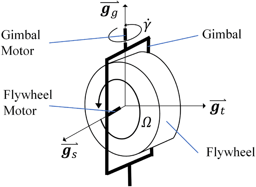
Control Moment Gyro Logic [ResearchGate]

2) Mechanical build

The frame holds a high-speed flywheel on a gimbal so the rotor axis can be reoriented quickly. Small errors in shaft alignment, bearing seating, or gear mesh add up, and that tolerance stack-up shows up as misalignment and vibration.This introduces delay between the motor command and the actual torque applied, which can lead to oscillation and noisy IMU readings.

Gear mesh testing

Photo placeholder (rotor balancing / vibration testing)

Photo placeholder (electronics + IMU)

3) Sensing and control loop

The IMU estimates tilt angle and angular velocity. A controller converts that error into a desired gimbal command (angle and/or rate). I’m tuning this to reduce overshoot and stop the “wobble” you get when the response is too aggressive.

Current tuning focus

  • Filter IMU noise without adding too much lag
  • Limit gimbal acceleration to avoid exciting vibrations
  • Choose gains that stabilise without oscillation

4) Results and next steps

The mechanism works and can produce enough torque to make stabalising corrections. I am currently tunning the PID controller and trouble shooting as the robot is not self balancing yet.

What worked

  • Higher rotor speed = stronger corrective torque
  • Stiffer mount reduced oscillation
  • Basic PID got first stable “hold”

Next iteration

  • Add saturation limits + anti-windup
  • Improve IMU fusion / filtering
  • Measure response and log data for tuning